
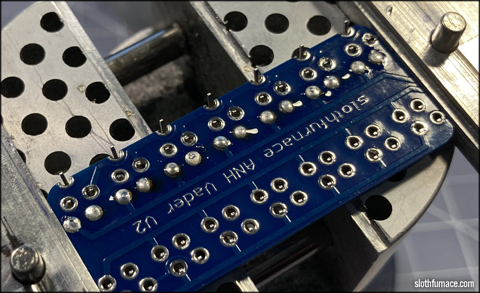
Here I will go through my assembly process for the ANH Vader V2 clampcard, using vintage correct "A" style LEDs from new old stock.

I was able to source quite a few of the late 1970s era LEDs still on the manufacturing rail, as was used on the Exactra calculator variant display board used on Vader's V2 saber seen briefly in A New Hope.
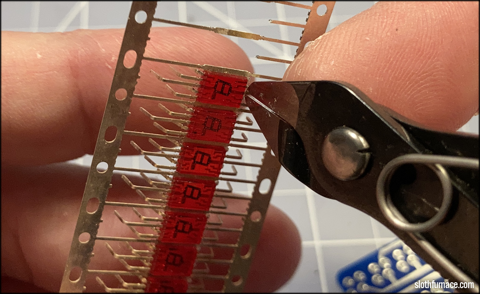
I take my sharpest, best Knipex nippers, and carefully separate each LED from its home.

I arrange them in order from when they were removed, keeping them in sequence relative to when they were made. They've been together for almost fifty years, so it's good to keep them together.
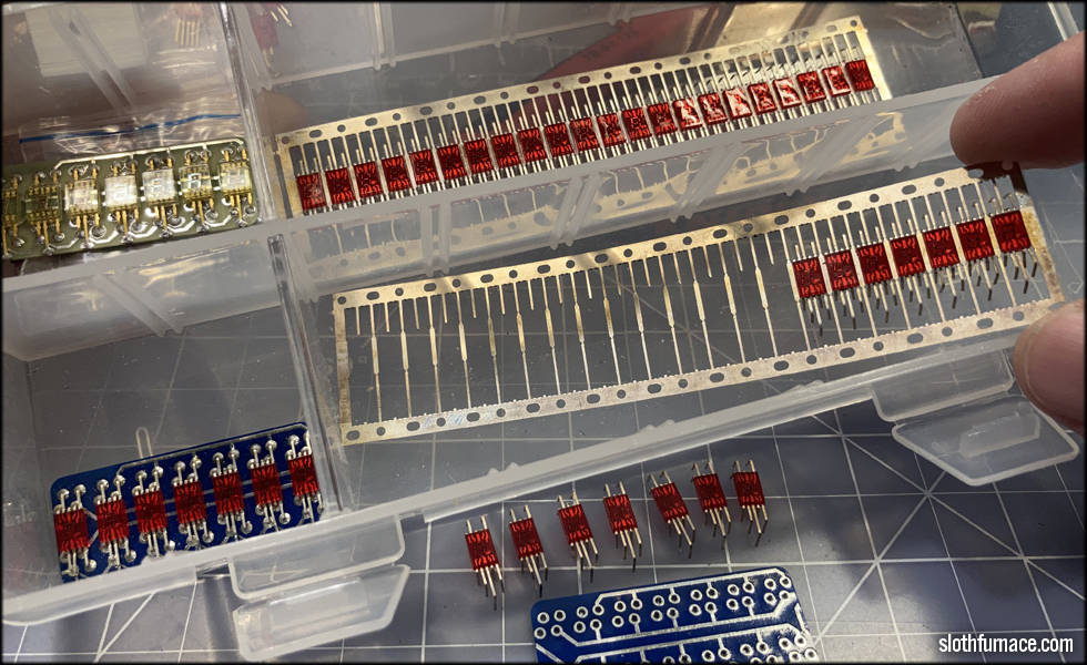
The last seven of this rail will be kept for later, and place back into my stock container, where I keep my last completely intact rail and other parts. If you notice, the "A" style LEDs are ever so slightly narrower than the current "C" style LEDs I've been offering lately in my shop. The internal components and materials are extremely similar, but the red plastic case they're cast in is just a touch wider. The "C" style also do not have pre-bent leads, so I had to 3D print a tool to do that job.
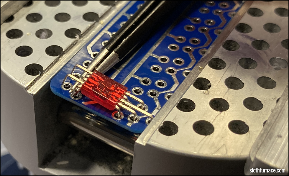
I carefully slot the long lead into the hole in the bottom of the board, and lay the LED down, feeding the leads into the proper holes. The first of the top leads must be slightly bent to feed properly...

Then the last two leads as well at the top.
I take great care in handling these LEDs as even just pressure from my fingers from picking them up can bend the leads out of form.
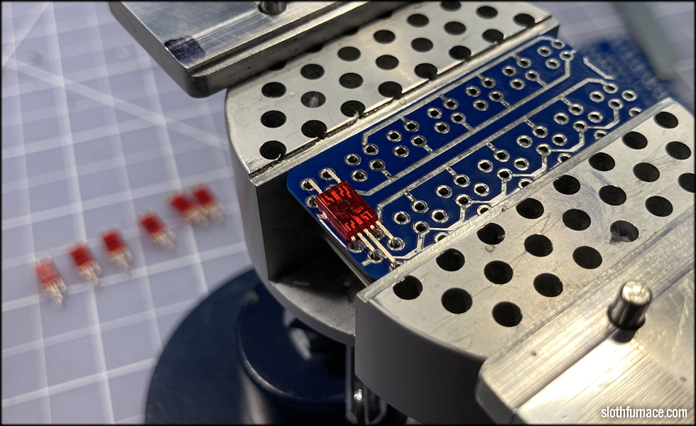
They're VERY delicate. The first LED placed, I move on to the second...

...and repeat the process.
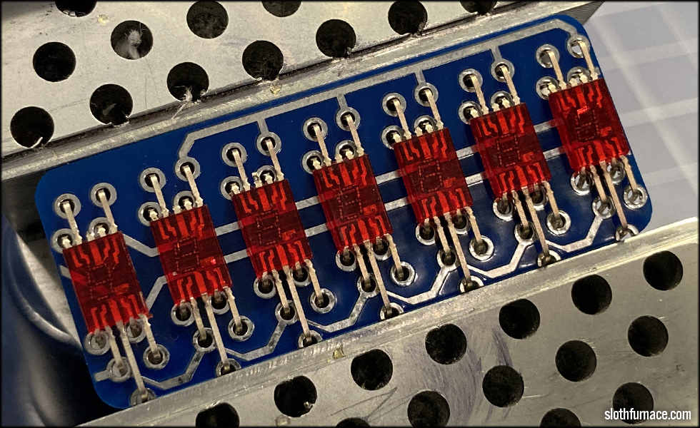
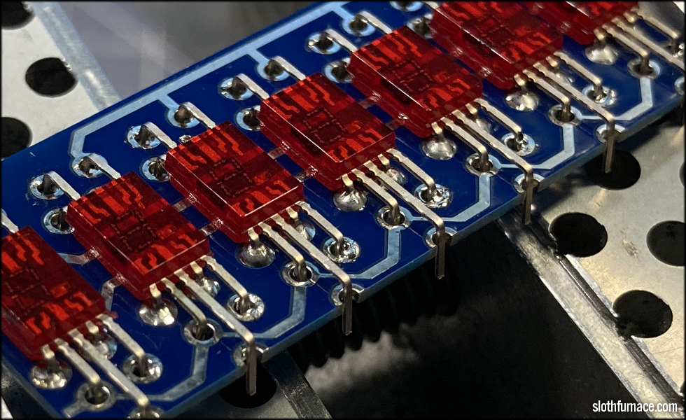
So on and so forth till the last of the seven LEDs is placed.
All seven in, and it's time to tack them in with a tiny bit of solder. I do this with extreme care so as not to get solder on the lead any more than is needed to stick the LED into place. I don't want visible solder to impact the appearance of this lead. I tap a tiny bit of solder onto the board bad and the edge of the lead.

Once each LED is tacked into place, I use a straightedge to check for alignment across the top...

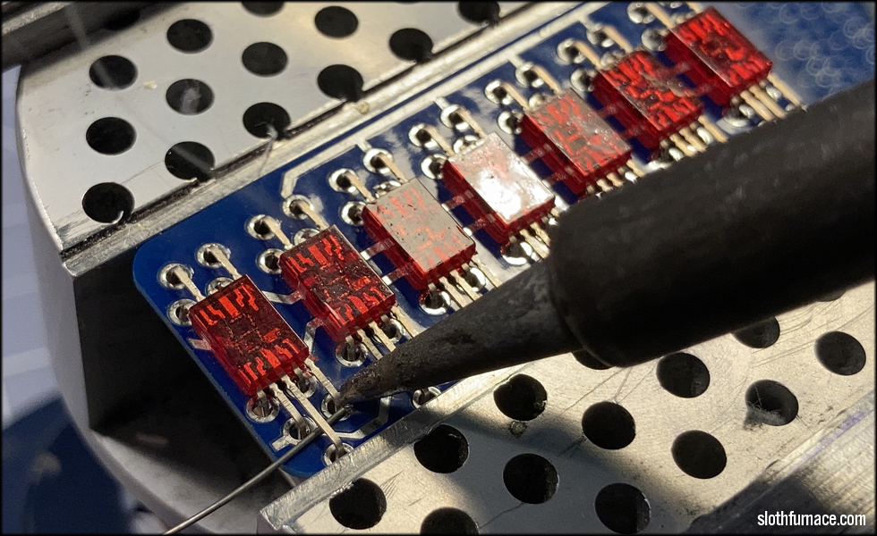
... and bottom and check for any LED that moves when I slide the straightedge back and forth. This shows me which one is slightly above or below the rest, and with my soldering iron, I loosen the tacked lead and reposition each one till they're as perfectly straight as I can get them.
The A style LEDs in particular are quite a lot more consistently formed than the B and C style, so they make for a very consistent install in terms of shape and size of LED plastic and leads. It is a real shame I can no longer source these.

Once I am satisfied with the layout and spacing of the LEDs, I tack the other side, on the opposing lead in the same way I tacked the first side.

At this point, I press on each LED, as I loosen the solder at the tack joint to make sure each LED is flush with the surface of the board. I usually hear more than one satisfying "pop" as I do this and each one is seated flush and square.

These are as square and even as I can make them, making sure each lead from each LED is centered in each hole in the PCB.
Now, before I can solder them all in, I need to pre-trim the leads flush with the back of the board. This may seem like an unnecessary step, but it will pay off later with a smooth back that will not snag on anything.

Cutting each lead flush with the board will allow a more even solder surface when done, and will make things consistent.

Nice and flush, nothing really protruding other than the seven long leads that go to the edge of the board, which I'll take care of later.

You can see here why cutting the exess lead material off flush with the board is important. It leaves a nice smooth dome of solder when done, and not irregular cut marks to the leads after soldering.
The inside row must be done first. If I do the outside row first, I'll loosen the bit of solder that secures the LED to the board from the first few steps, and I'd lose the work done to make things evenly spaced and square.
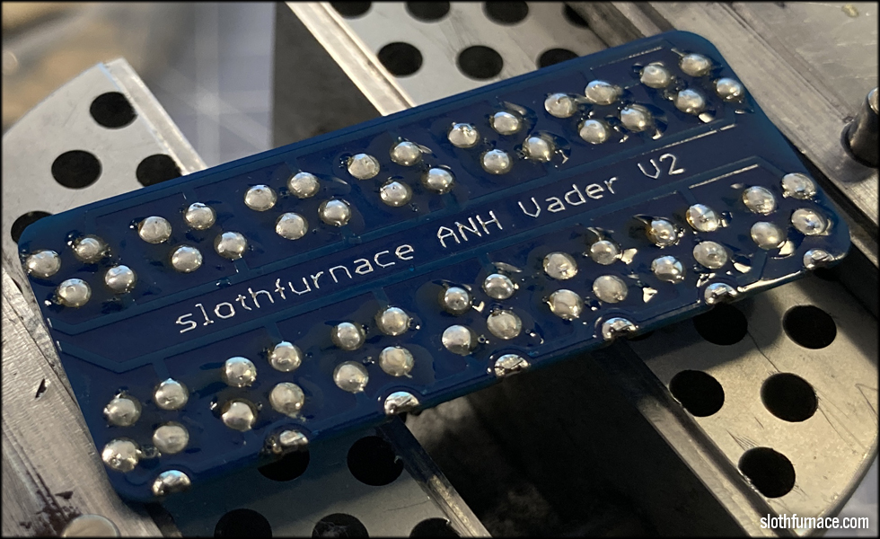
I flip the board over to check my work. Consistent amount of solder fed into the joint will produce the proper dome shape on the other side. I never know if I've done the job correctly till I flip it over, and so I have learned to go by feel as much as anything on this.
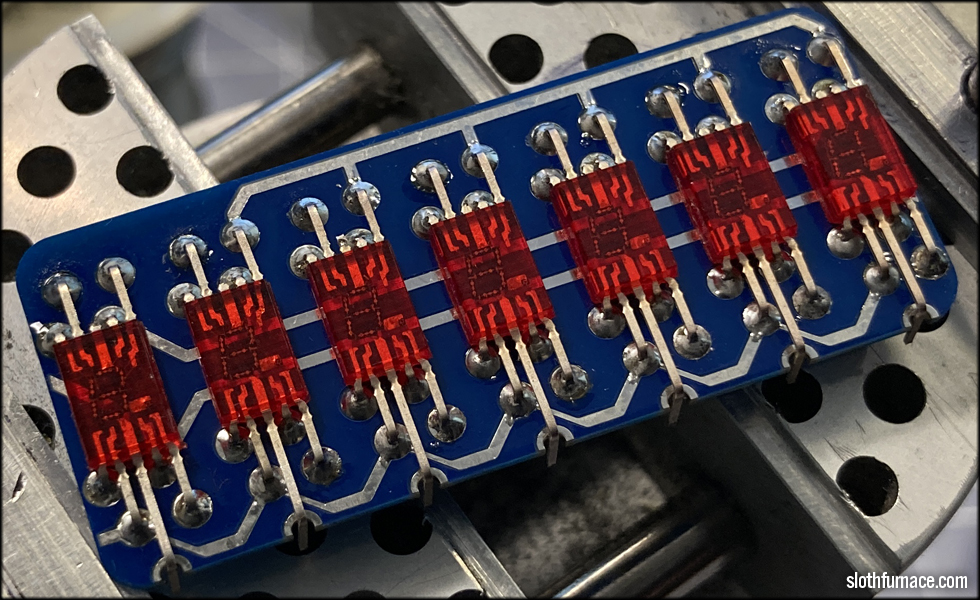
Securing the other inside row, then the two outside rows top and bottom with the same amount of feed to the solder when I apply heat. I try extremely hard to make each dome the same size and shape as the molten solder flows through the board and slightly down the LED lead to form that shape. The more consistent these are, the more similar to the original vintage part.

Now is time to add some solder to the seven outer leads, and the half circle vias on the edge of the board.

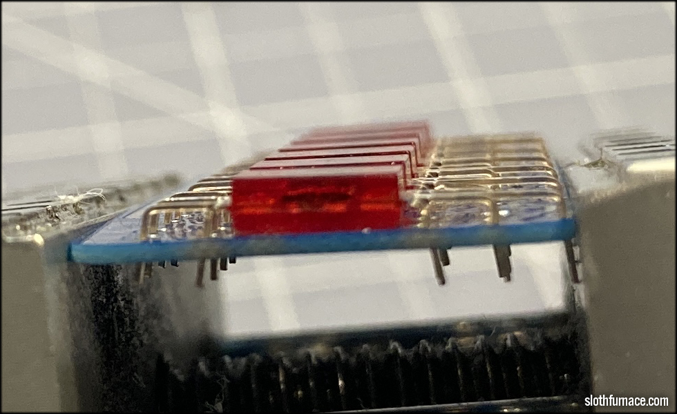
These are now soldered, but I need to lower each one so the board fits the MPP clamp.
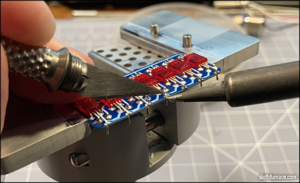
With a hobby knife, I gently press on the end of each lead as I heat the joint with the soldering iron. This will allow each lead to be pushed down to the surface of the board.

And then I trim off the excess.
A nicely soldered board ready for cleanup. The flux from the solder needs to be cleaned from the back of the board.
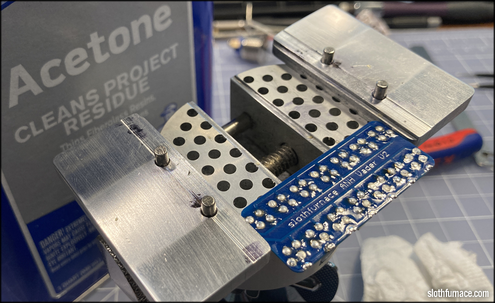
I've found that on these boards, acetone and a bit of paper towel works best.
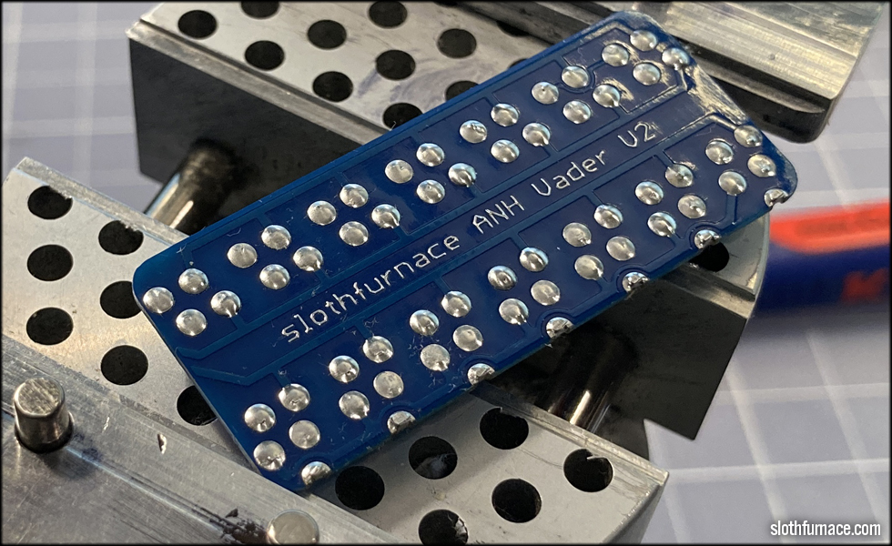
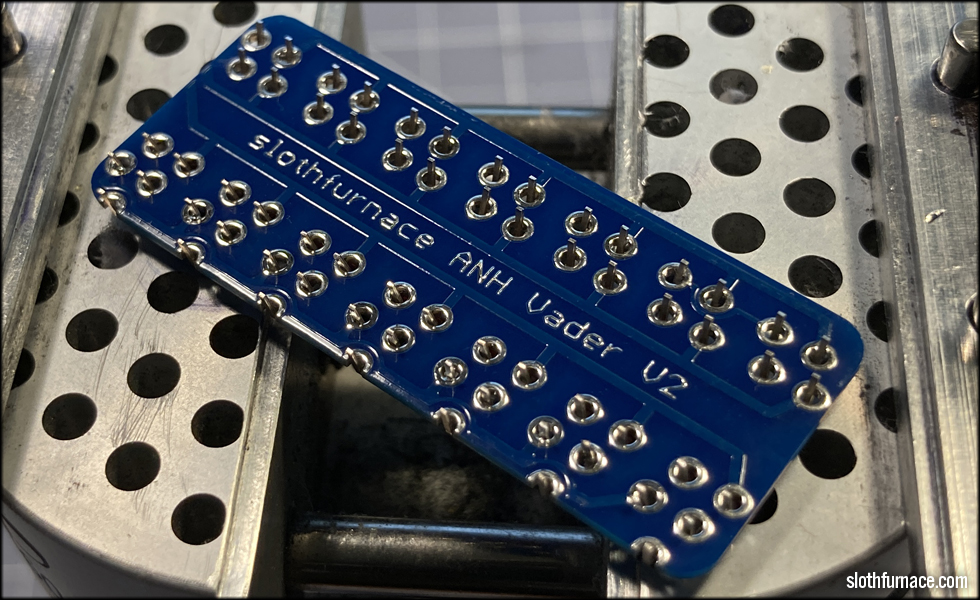
There! A nice clean board and clean, smooth solder domes.
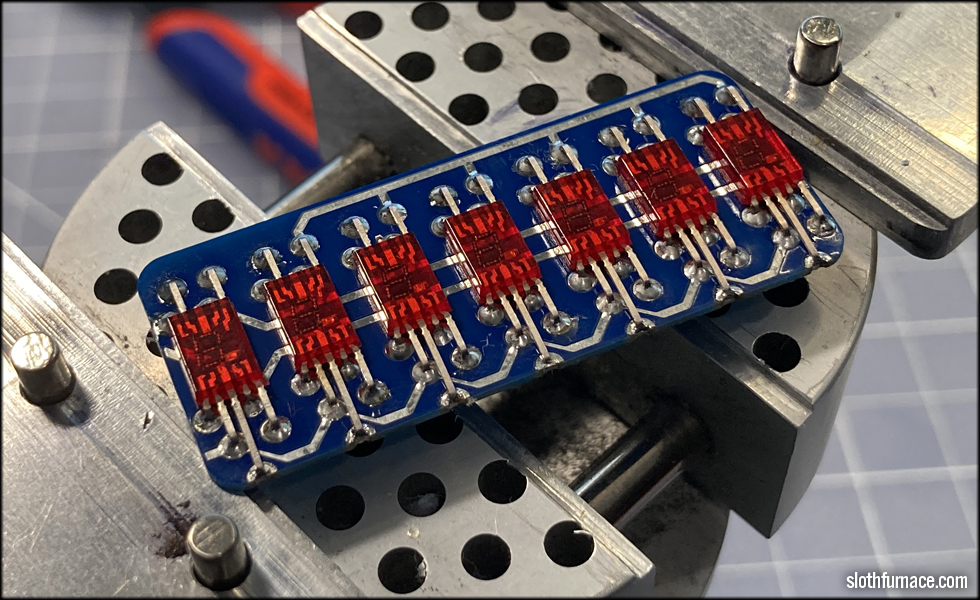
And there we have the Slothfurnace ANH Vader V2 "A" style vintage LEDs on the blue PCB, ready to ship!
This site is part of the nonentity network. Not associated with LUCASFILM LTD.™ or any LFL Ltd.™ Film or Franchise.