
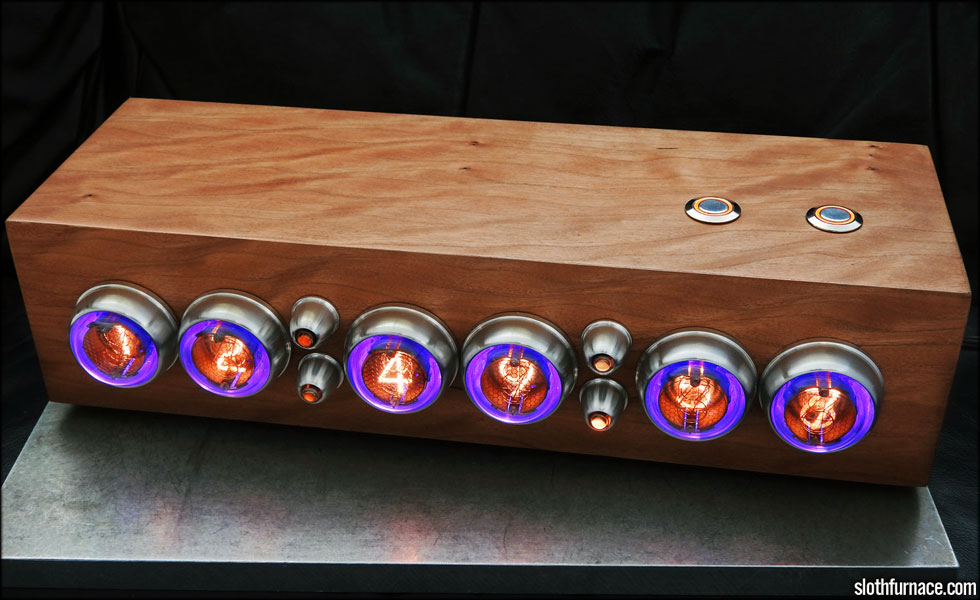
This is a nixie clock using six matched vintage Valvo ZM1020 numerical indicator tubes, four Russian INS-1 neon lamps, two 16mm orange LED illuminated vandal switches for set/dim, six Adafruit neopixel modules for the RGB backlights which are driven via wifi enabled Electric Imp unit.
This clock pings weatherunderground for local weather conditions, and changes the tube backlights based on the weather in its zip code. Blue for cold, red for warm, flashing blue for rain, flashing white for lightning, scrolling white for fog and ice, etc.
The box is a great piece of quilted cherry with Arm-R-Seal polyurethane to seal the wood. It's been sitting unsealed for about 10 months under the kitchen lights to let it darken up a bit. It will darken more over time.
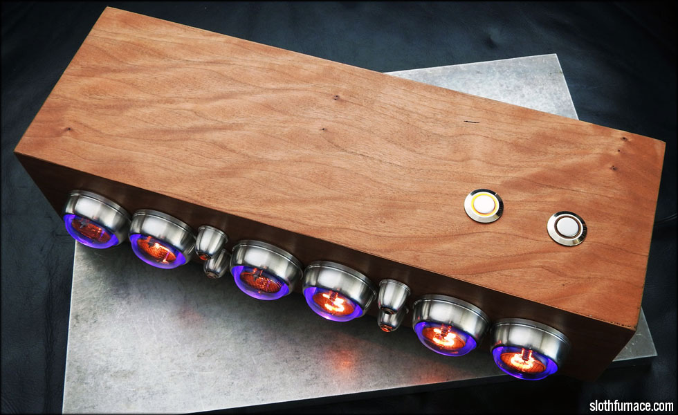
The quilted cherry really shines now, it's tough to get a good photo of how the grain catches the light. It's really nice in person. Last steps include the back metal plate and some rubber feet.
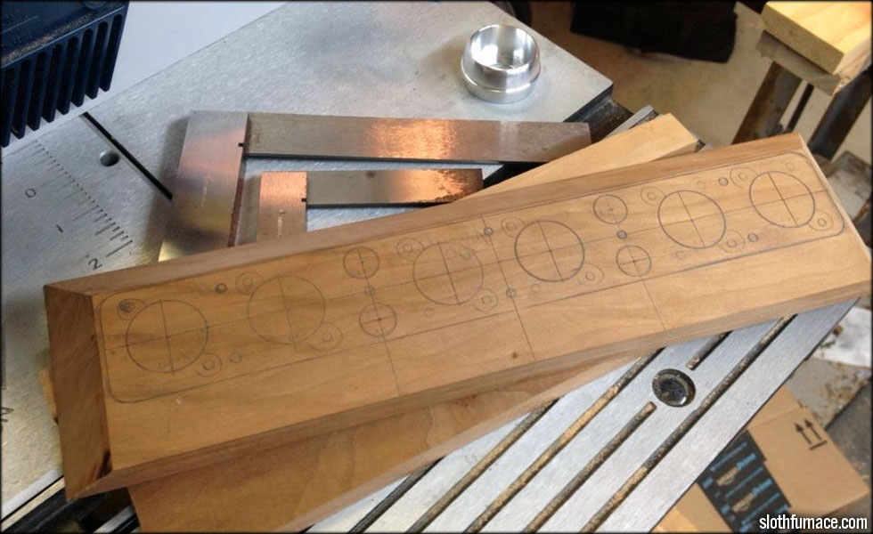
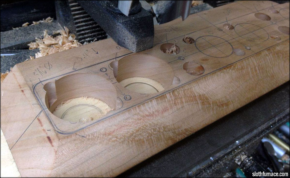
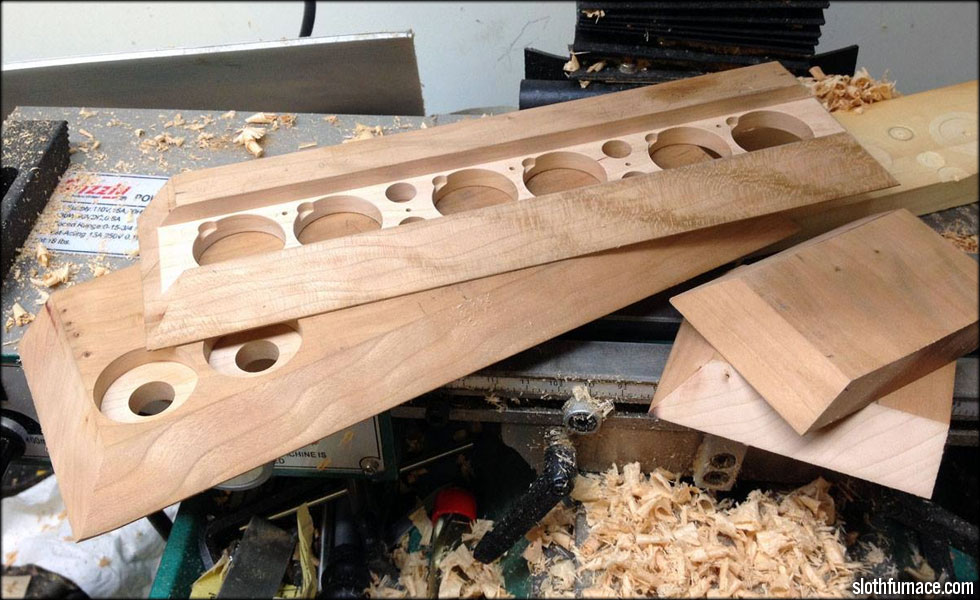
I started the box by laying out the holes for the front face. Here you see my clearance holes for the tubes, the tube socket bolt heads, the mounting screw holes for the socket plate, and the colon bezel holes.
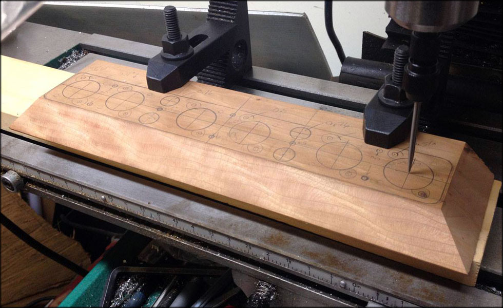
Here I am centering on my layout marks. I have squared up my stock on the big milling machine to make the next few operations as square as possible. I hope to do most of the back milling work on the clock face here.
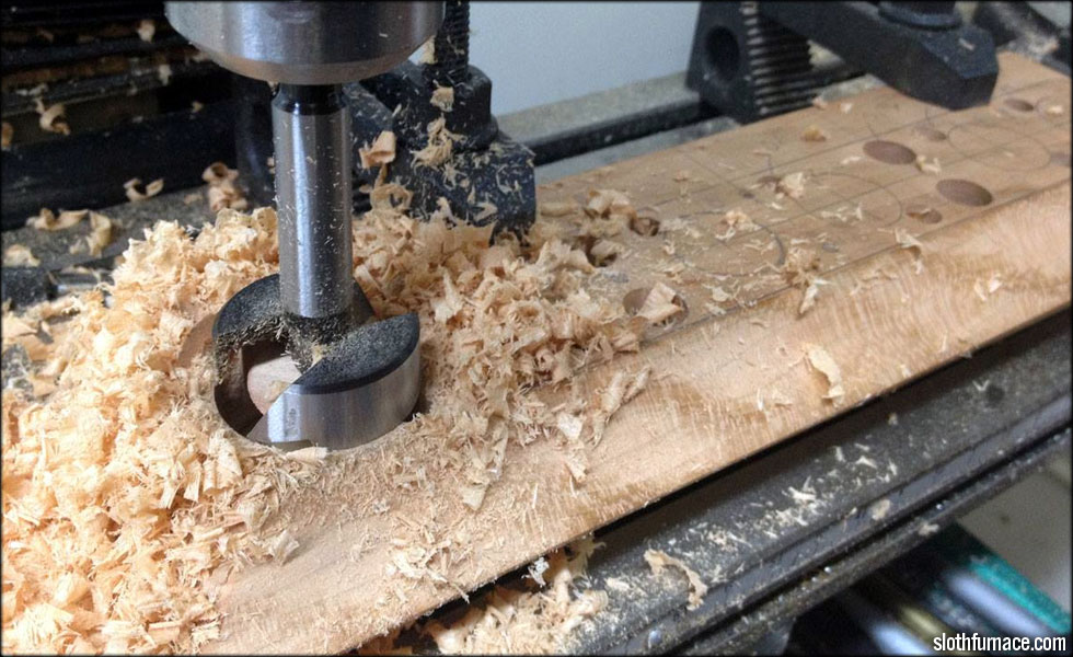
Here I am using a forstner bit to bore out the nixie tube clearance holes. I use this kind of bit because it gives a very good finish to the holes.
Next step is milling out the clearance ears for the socket bolts. The socket bolt heads will sit inside these recesses.
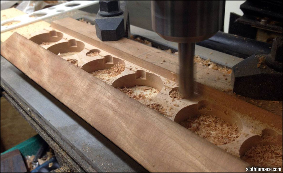
Here I am milling out the socket plate channel. The socket plate will hold all the tube sockets to the clock face. It has to be set a certain distance from the outside face of the clock so the tube leads will seat properly into the tube sockets.
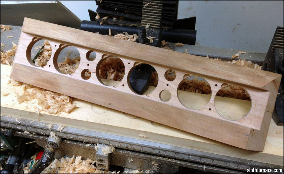
Now all the holes to mount the tube socket plate are drilled and milled. I can now move on to the top of the clock box and countersink the holes for the set and dim buttons.
I will be using some orange LED illuminated 16mm AV switches for the set and dim funtions. I drill the holes for these in-line with the two seconds display tubes. I bore out the underside of the clock box to accept the button hardware.

The most panic inducing and nerve frazzling part of building one of these clocks. The ominous, point-of-no-return that is gluing up the box. If it's wrong, it's ruined.
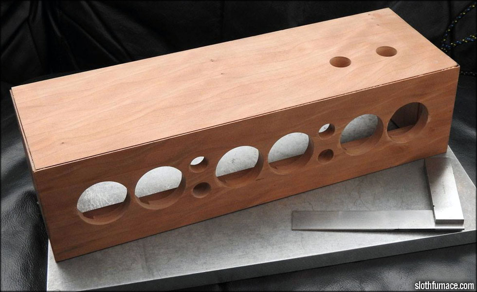
Well, I am no carpenter, but I make do. The corners ended up being more square than they have any right to be. I'm pleased with it at this point. I'll let it sit for a while and start sanding/scraping it down to remove any surface nicks or dings.
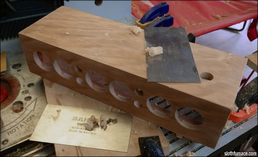
Scraping done, I'll move on to the electronics next.
This site is part of the nonentity network. Not associated with LUCASFILM LTD.™ or any LFL Ltd.™ Film or Franchise.