
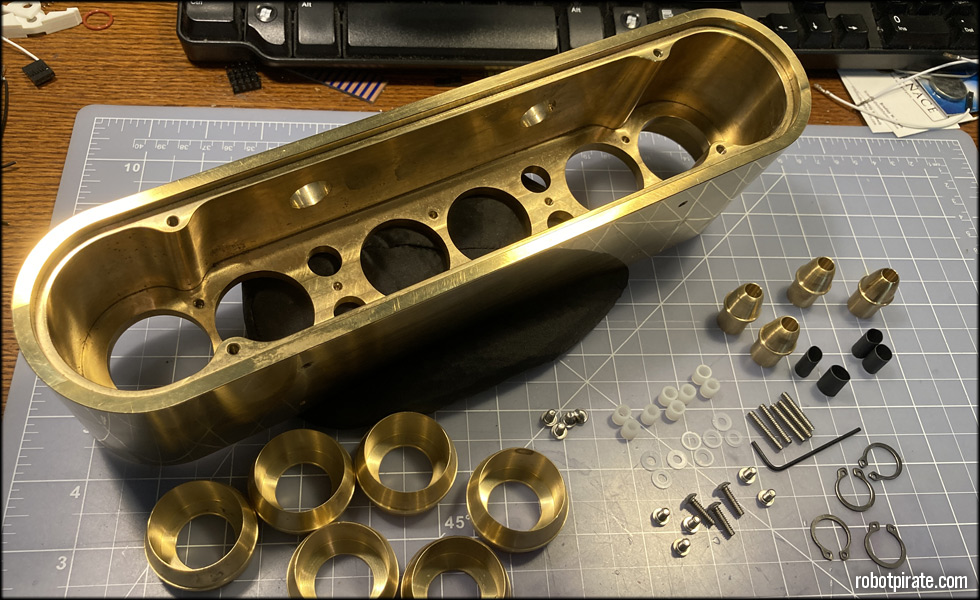
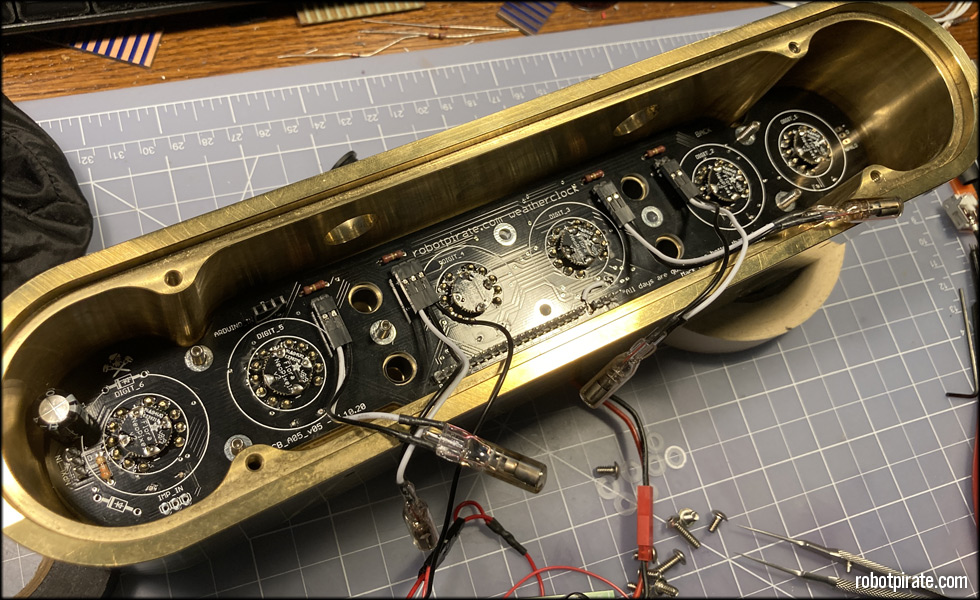
This is the clock case I'll be assembling. This particular one is in solid brass, machined by my friend Philip Wise at New Wookiee Workshop in Roanoake, TX. The hardware I've assembled is as follows:
1x solid weatherclock case in brass
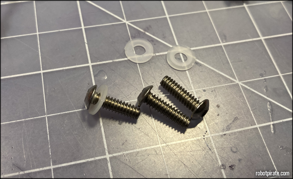
4x 1/4 inch 6-32 stainless cap screws for the back plate
8x 1/4 inch #6 nylon spacers for mounting the display board to the clock case with enough room to account for the colon separator lamp bezels
8x #6 nylon washers
5x 1/4 inch 6-32 stainless cap screws for mounting the switch boards to the clock
3x 1/2 inch 6-32 stainless cap screws for mounting the display board to the clock
5x 3/4 inch 6-32 stainless set screws for installing in the clock, going through the switch board, and into:
5x 5/8 inch 6-32 aluminum female standoffs for mounting the switch boards
4x heat-shring tubing sections for inside the colon separator lamp bezels to cushion the glass lamps against the brass
4x 15/32 inch spring clamps to retain the lamp bezels against the back of the clock face
4x brass colon separator lamp bezels
6x brass nixie tube bezels
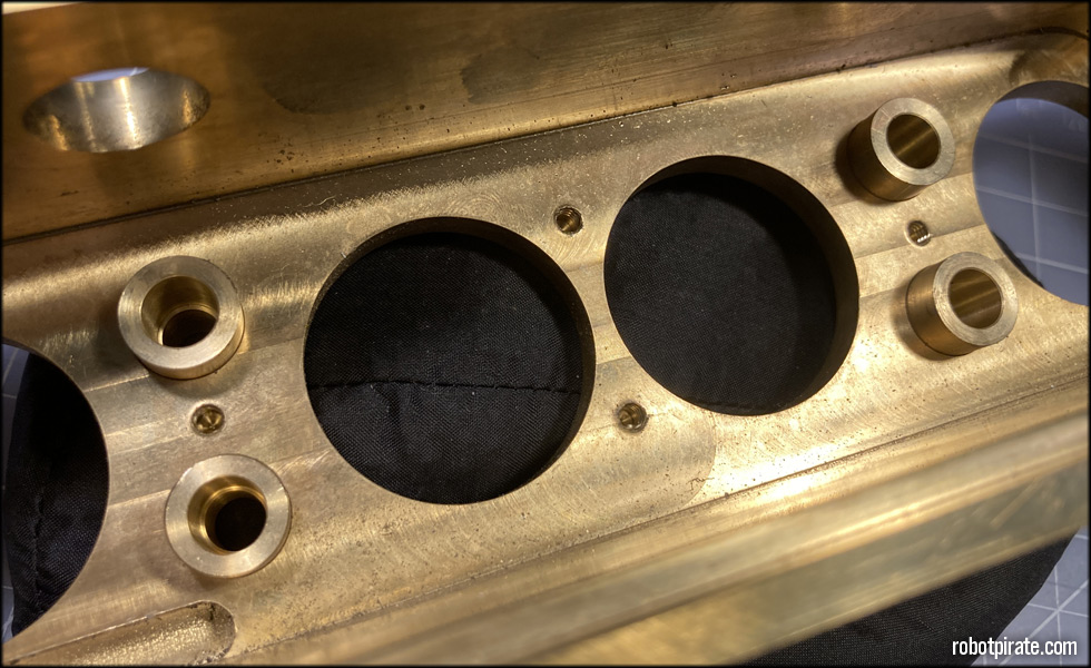
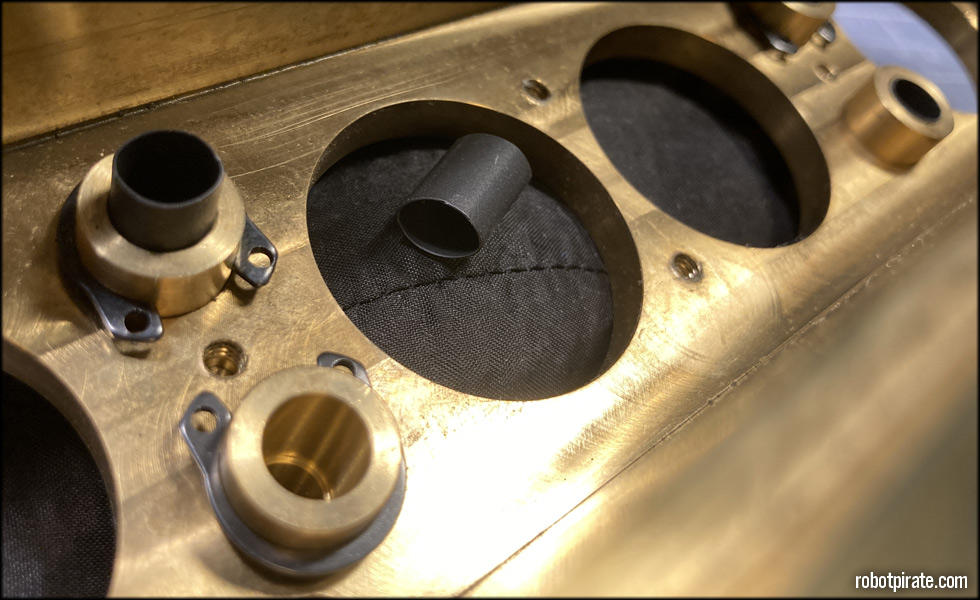
First, I'll insert the colon separator lamp bezels from the front of the clock face.
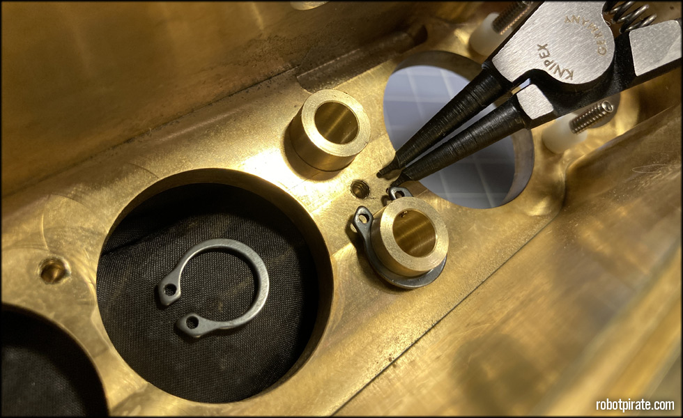
And then with the proper spring clamp pliers, affix the spring clamps to the 1/2 inch diameter bezel section that protrudes from the front.
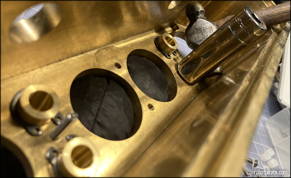
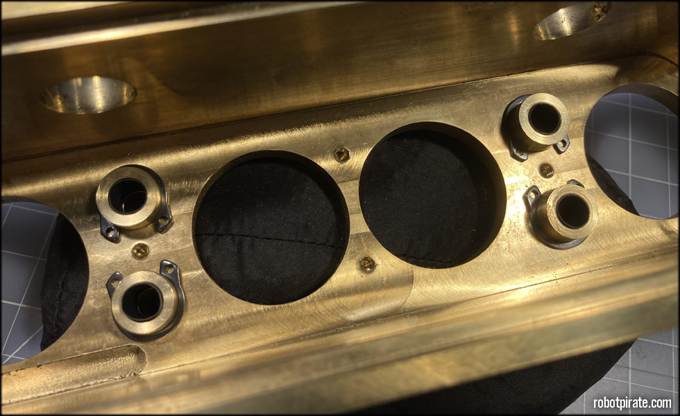
A little light tapping with a hammer and a #13 Snap-On deep well socket as I press on the bezel from the front and they're seated firmly.
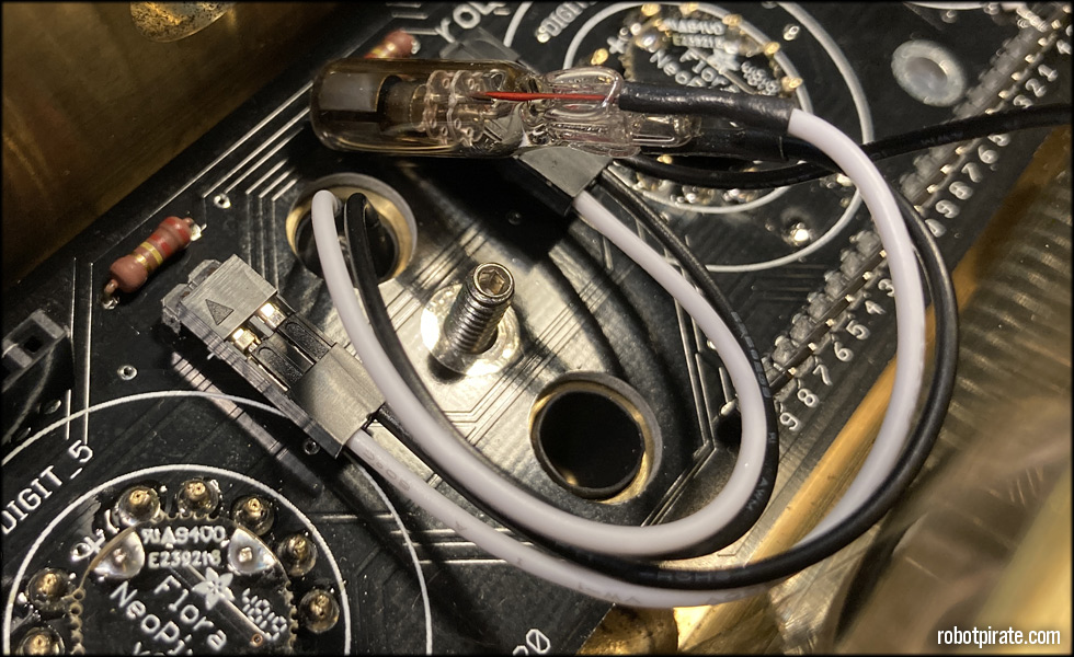
This is where the larger diameter heat-shrink tubing from the lamp wiring step comes in. It keeps the glass lamps from touching the brass bezel, cushioning them away from the metal, while giving a snug fit so they stay in place.
As I stated earlier, these INS-1 lamps vary widely, so if they don't provide a snug enough fit, a bit more tubing or insulation around the glass will allow for a snug fit.
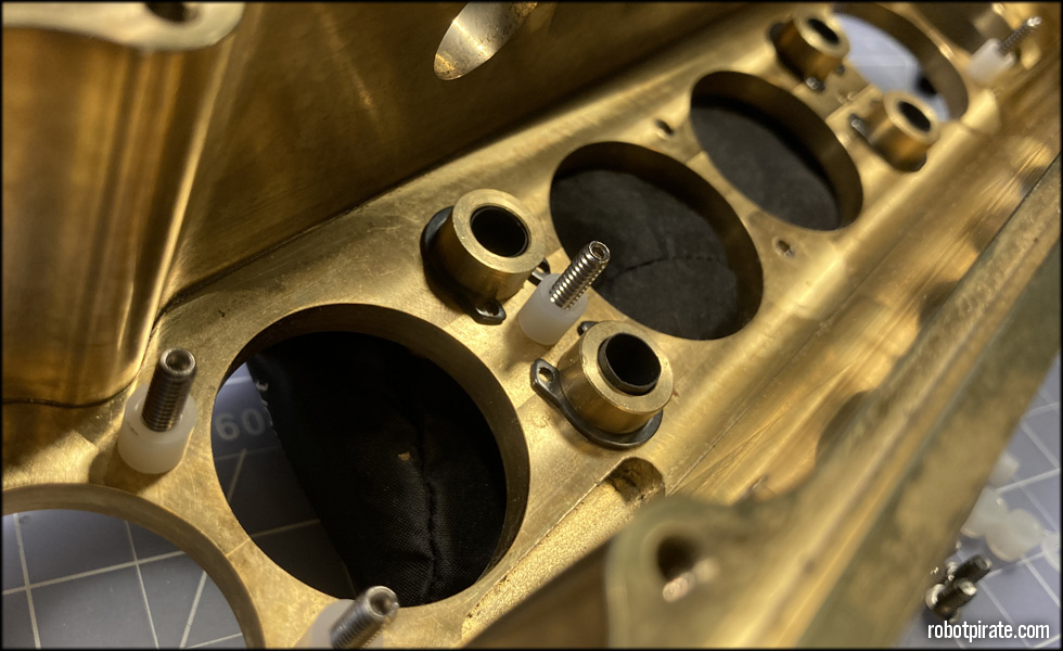
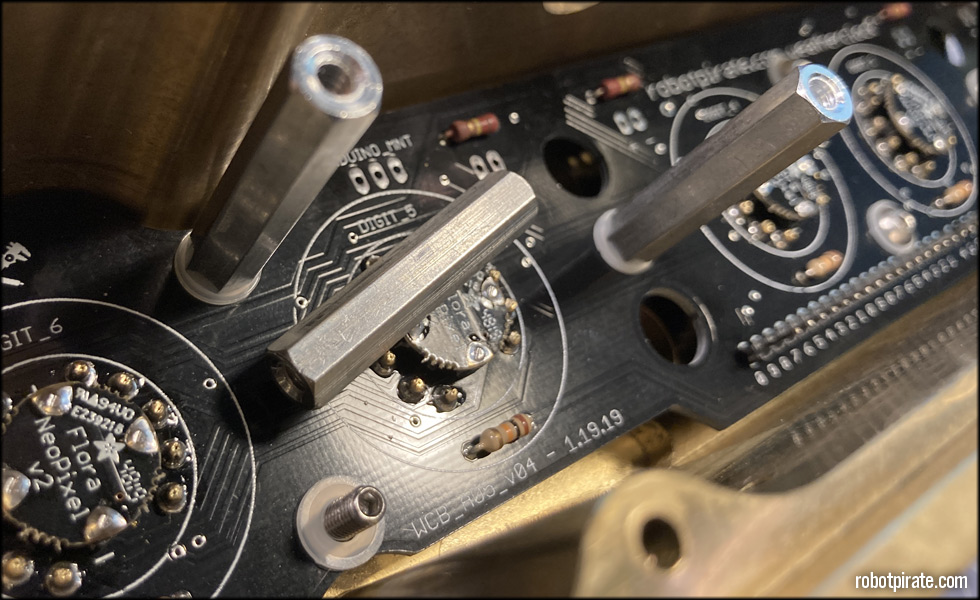
Now the 5x 3/4 inch 6-32 stainless set screws go in to the threaded holes on the rear of the clock face. Once in, I place five of the 1/4 inch nylon spacers over them.
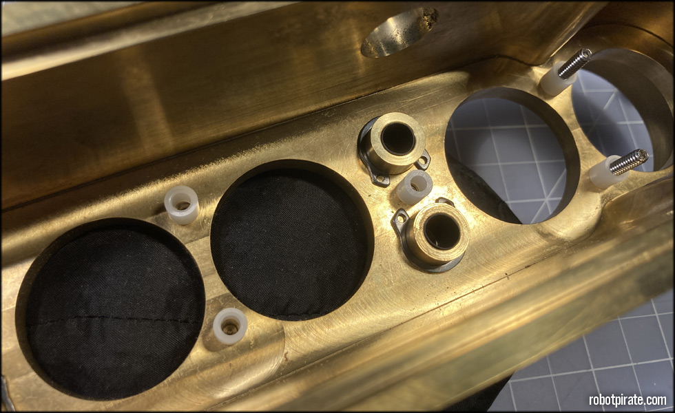
The other three nylon spacers get placed over the threaded holes and I steady the clock so they won't get displaced when I lower the display board down over them.
The display board comes down over everything and is aligned via the 5x 3/4 inch 6-32 stainless set screws.
With the display board in place, I carefully push the INS-1 lamps into the bezels from the back, making sure they're a snug fit inside the heat-shrink tubing that is installed in the bezels.
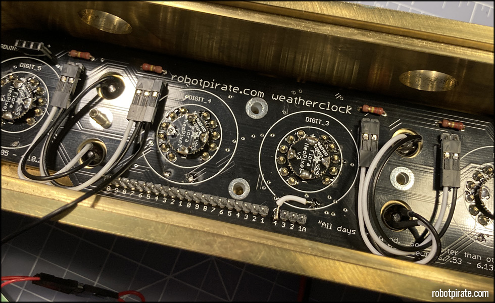
All four lamps installed, I will next use tweezers to align the 1/4 inch nylon spacers with the screw holes.
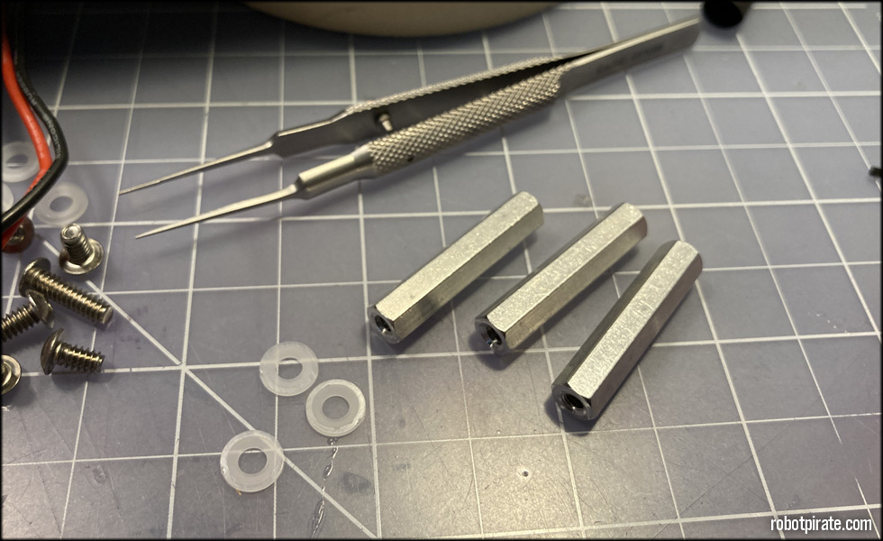
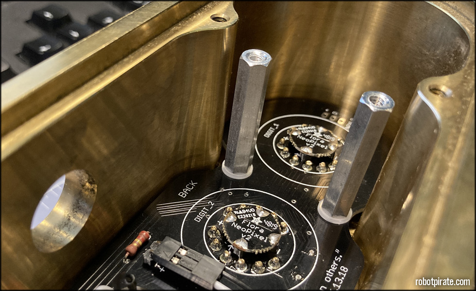
These 5/8 inch 6-32 aluminum female spacers will be threaded on to the 5x 3/4 inch 6-32 stainless set screws, after these #6 nylon washers are placed.
These nylon washers and spacers not only protect the display board, but also space everything properly so it all fits behind the back plate.
Three on this side, which will support the switch board that controls the Weather and Animation backlight modes...
And two on this side, which will support the switch board for tube sleep and battery backup off state.
These three 1/2 inch 6-32 stainless cap screws and three nylon washers round out the display board install hardware.
Now the display board is secured into the clock, we must install the rest of the components...
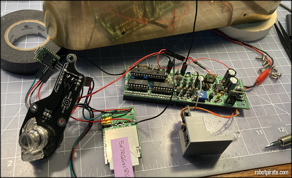
...which include the switch board, the Electric Imp April board, the main driver board and the battery backup.

I start with pin 0 of the very leftmost cathode bank, and then gently press the driver board down on to the display board header rails.
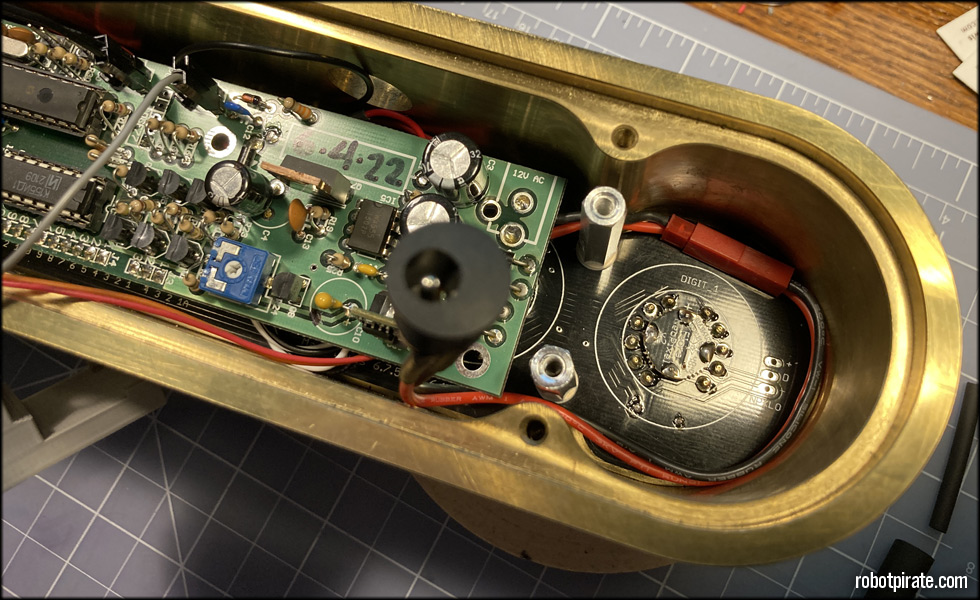
Here I route the main power feed from the power jack around the aluminum spacers to give room for the tube sleep switch.

Then I install the Electric Imp April board into the slot milled in the back of the clock face, underneath the display board.

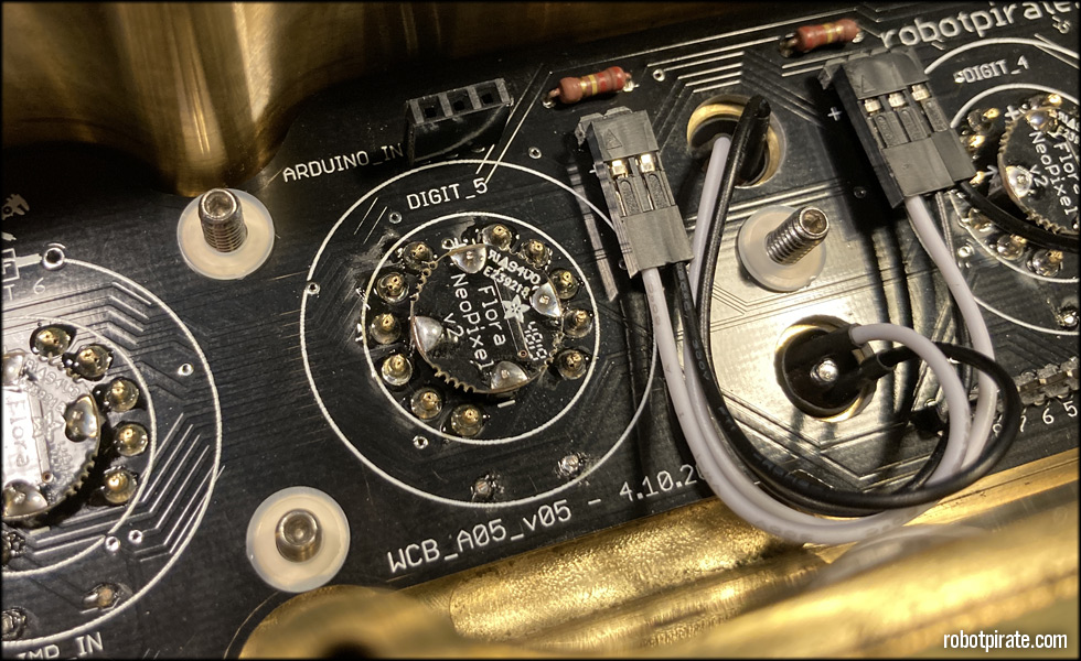
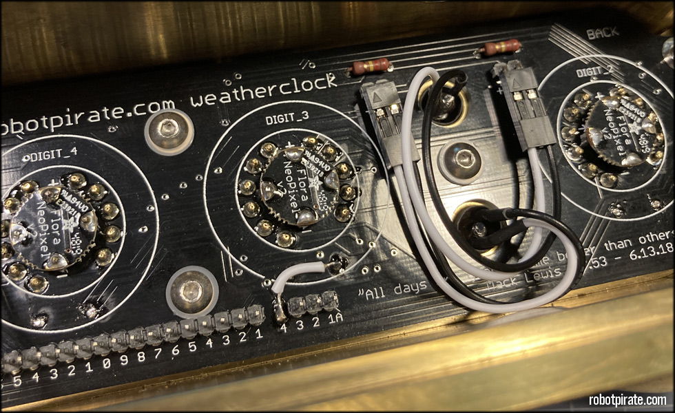
Then I plug in the power and data cable from the backlight mode switch board to the NeoPixel input of the display board.
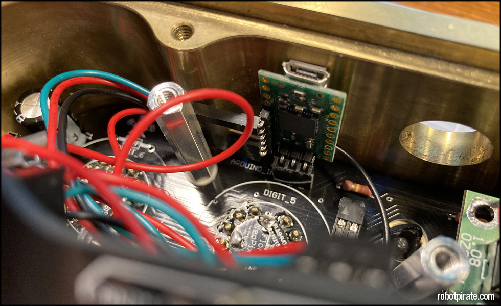
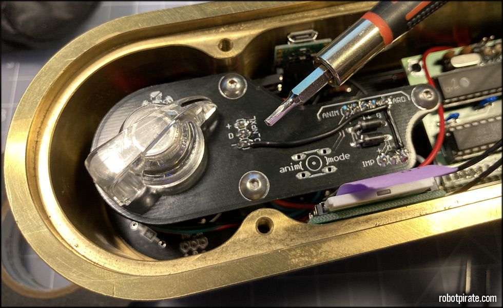
Next the Arduino for backlight animations is installed...
And the backlight mode switchboard is screwed in to the aluminum standoffs using three of the 1/4 inch 6-32 stainless cap screws.
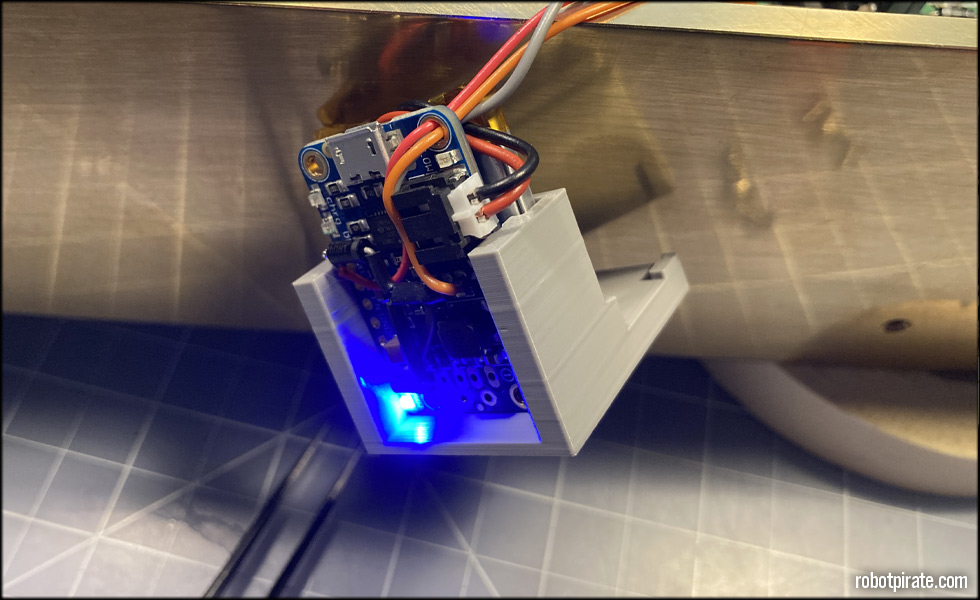
Here the battery backup module is ready to be installed...
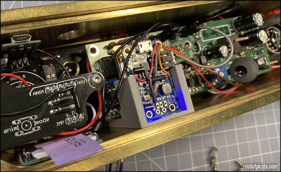
...by placing the back tabs under and behind the main board.
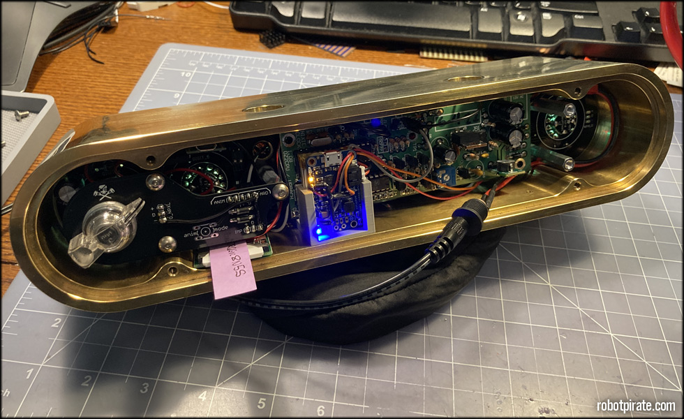
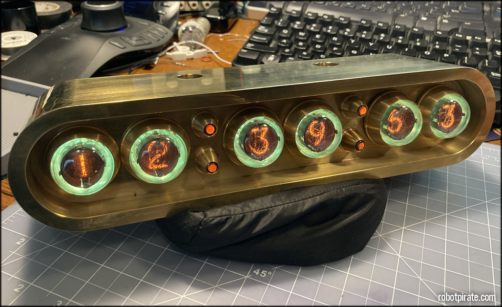
A quick power-on test...
And all lights are green! Meaning, it's about 75 degrees F outside. The weather display changes colors based on temperature and weather conditions.
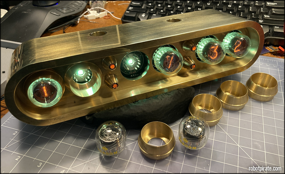
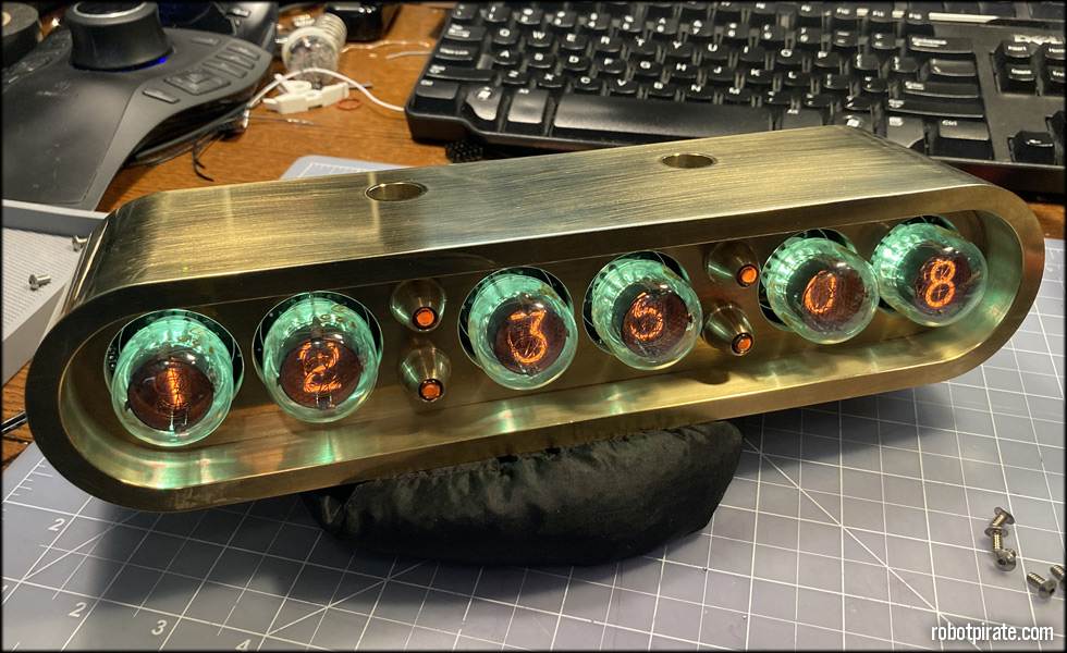
Now I carefully pull each tube out, install the brass tube bezel, and re-insert the tubes. The tubes themselves hold the bezels in.
And this part is done!
This site is part of the nonentity network. Not associated with LUCASFILM LTD.™ or any LFL Ltd.™ Film or Franchise.