
Here I will go through my assembly process for the Weatherclock display board. Mostly these are notes for myself so I don't forget how to do this in the future, as that has already happened and I've had to re-learn some of what I did on the original clocks to make them work. However, if you think this is interesting, read on!

To start with, I take the z560m x 6 display board, and lay out all the needed pieces. From top left, clockwise:
Spare tube with good, straight pins for pin socket alignment and installation
Section of pin header rail for cathodes
Arduino Mini
66x pin sockets for soldering to the board and holding the tube pins
Angled pin headers for colon separator neon lamps
4x1 header pins for neopixel board mounting
Adafruit Neopixel Flora x 6 for Nixie tube backlight/weather indicators
6x10k Ohm resistors for the anode connections on the nixie tubes
4x 220k Ohm resistors for the colon separator neon lamps
330 Ohm data line resistor for the Neopixel data feed
1x Main display board a05_v05
1x Neopixel capacitor
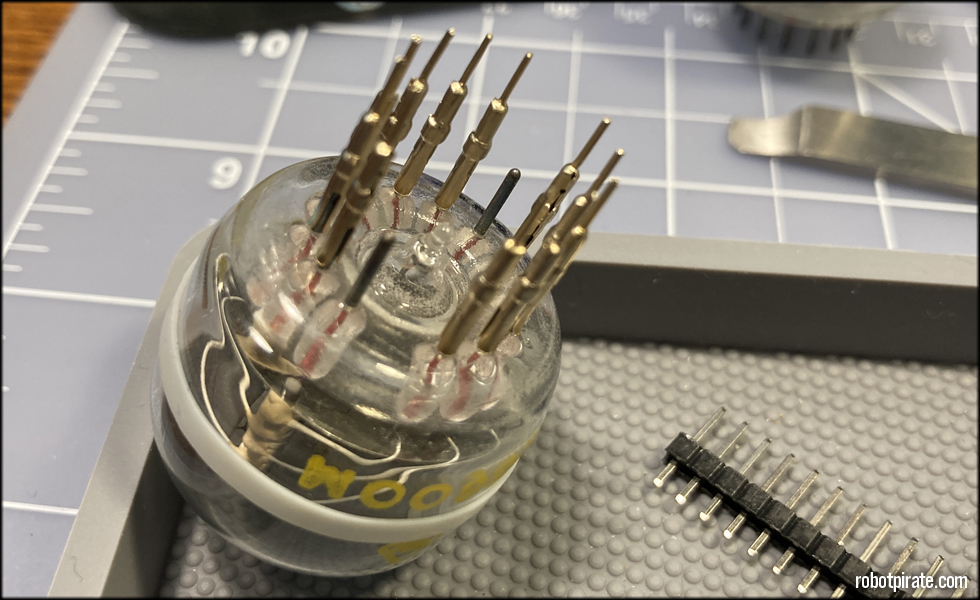
Using a z560m tube with good, straight pins, set 11 pins on the tube starting with the anode, skipping pins at 12 and 6 o'clock

I make sure the split in each pin socket is perpendicular to the center of the tube, that is the best way to account for variations in straightness of tube pin when the tubes are installed.
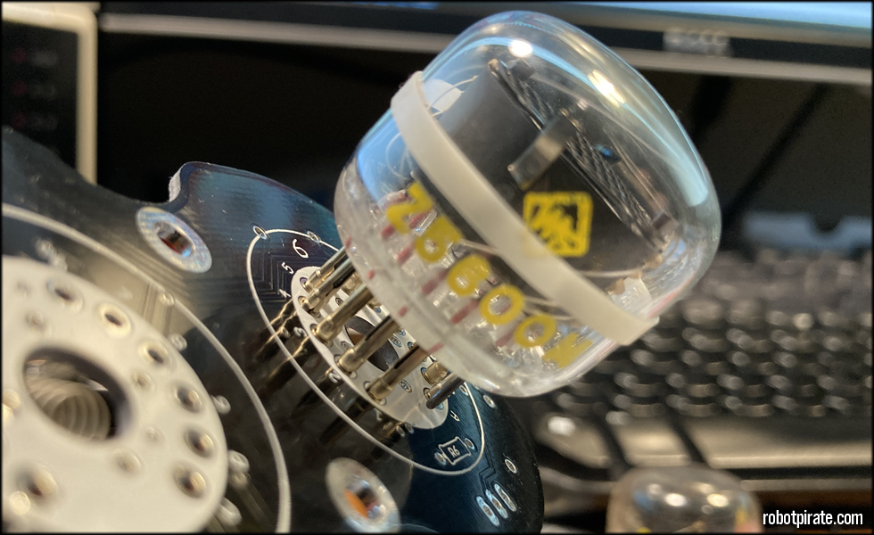
Then I place the pin socket array into the board and make sure it's square and straight.

Placing the tube into something round like an electrical tape reel or similar lets me make sure everything is even as I put even, gentle pressure on the tube so all the pins are seated properly into the board.

Soldered in, and ready to trim the excess material from the back of the pin sockets.
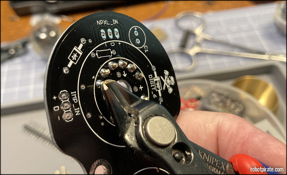
Carefully trim the excess metal from the pin sockets, as we don't need them and they could cause a short.
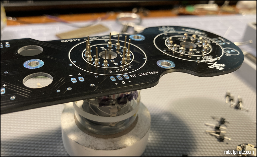
...and repeat the process.
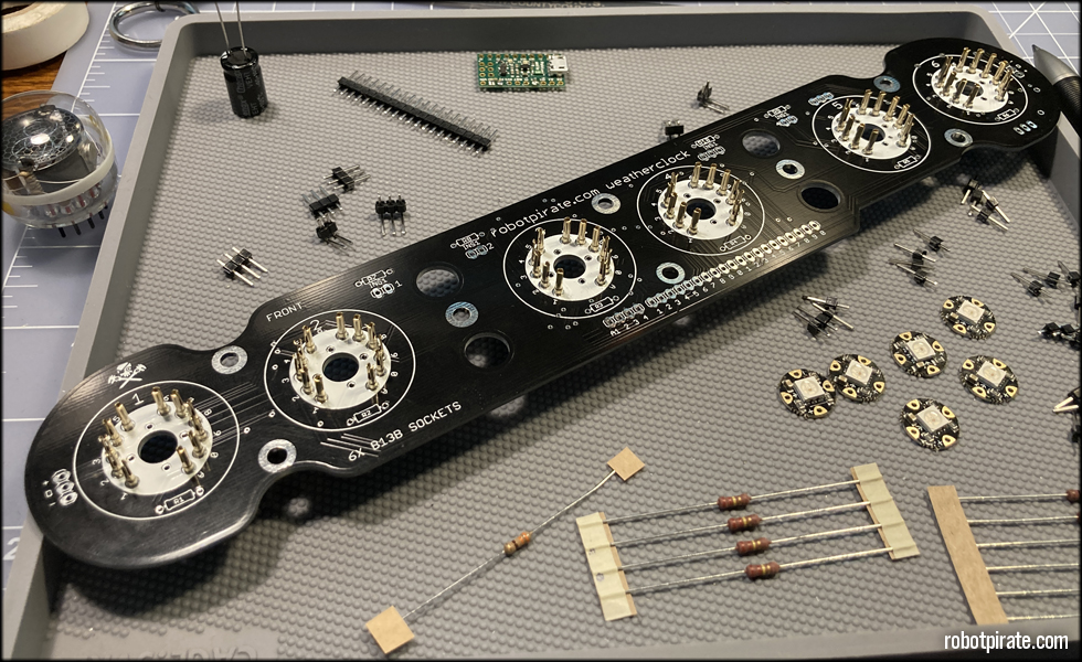
So on and so forth till the last of the pin sockets are placed.
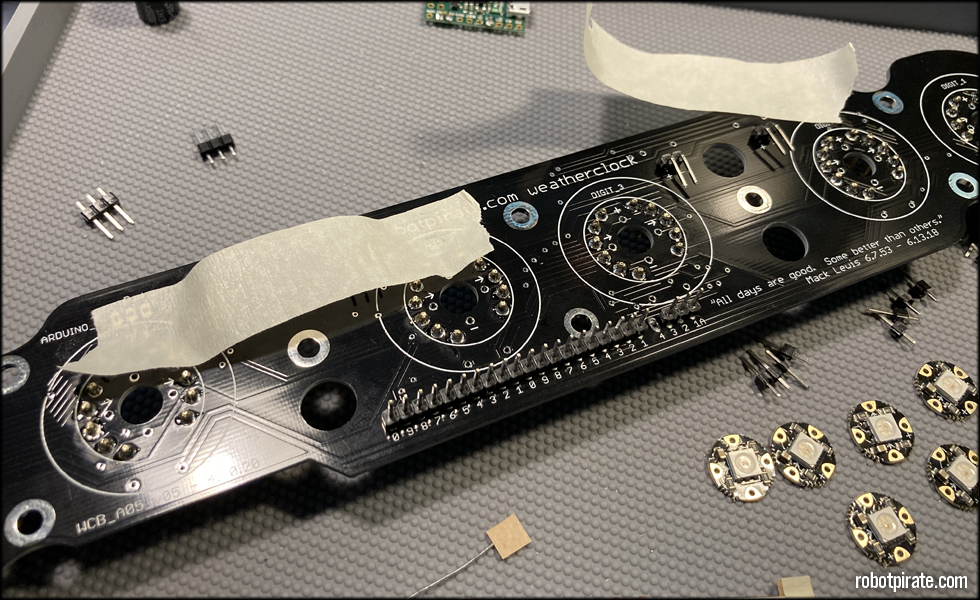
Next, I arrange the pin headers on the board, and lay a bit of masking tape over them to keep them in place while I solder tack them in...

... by soldering just one connection, then making sure they're aligned properly, and soldering the rest in.

The 330 Ohm resistor goes near the Neopixel input header (lower left blurry bit), and the four 220K Ohm resistors go near the colon separator lamp headers on the back of the board just to save room on the front. They could go front or back, no difference.
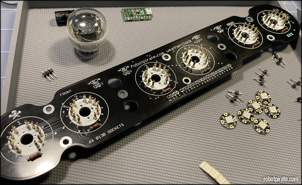
Next, the six 10K Ohm resistors go on the front of the board in places R1 through R6. Again, these could go front or back.
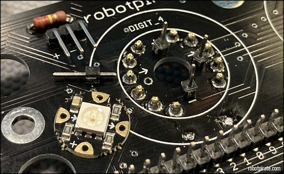
At this point, it's time to solder the single 1 pin headers to the four corners of the Adafruit Flora Neopixels.

Put the short end of the header into the board, and the long end of the header up. Place the NeoPixel board over them making sure the arrows, positive and negative pads line up.

I usually lay them all out at once, and then trim as follows...

Cutting each lead flush with the board will allow a more even solder surface when done, and will make things consistent.

Nice and flush, nothing really protruding other than enough header to get hold of with the soldering iron. Trimming these at this point is easier than trimming them after they've been soldered.
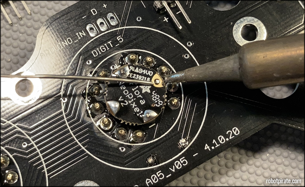
Solder them in, making sure to get even heat on the pad and the header pin, and make sure the board is even and square once soldered so the light will pass through the display board correctly.

These six have been prepped for installation, I usually take them from the board to do a final check before I install them.

I flip the board over to solder the short ends of the headers on the front side of the display board, and make sure they're flush, even and square so the light coming from the neopixels will shine into the center of the nixie tube once it's installed.
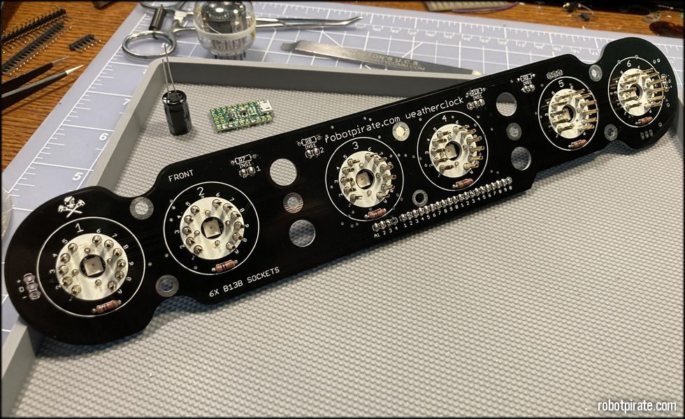
All installed, and ready for the next step.
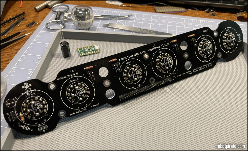
Here I am preparing to do the anode #4 jumper wire, and install the NeoPixel power capacitor.
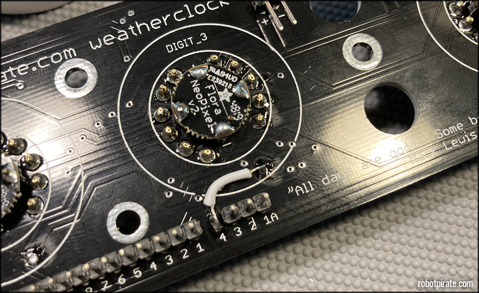
This jumper is for the neon lamp colon indicators. I jumper anode #4 over t o the incoming hot side of the resistor R3 for anode #3 on digit #3. I do this because the anode bank on the driver board I'm using doesn't have a fourth anode pin for the colon separators, and I'm pulling power from anode #3 to supply those lamps.
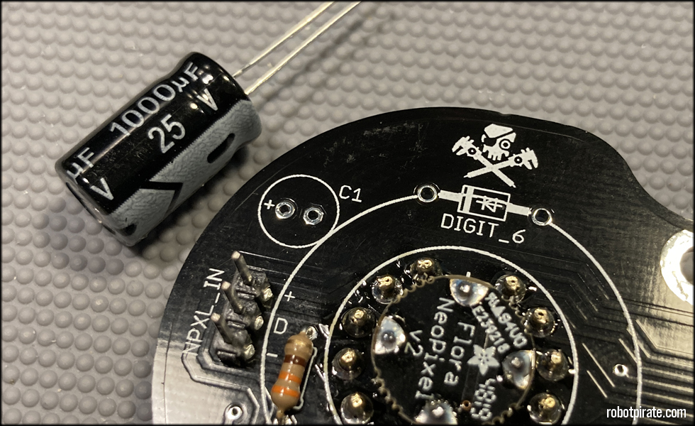
This is the NeoPixel power capacitor, a 1000uf 25v cap that bridges the positive and negative line for the NeoPixels, as per instructions from Adafruit:
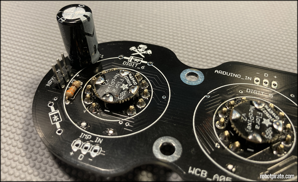
"Before connecting NeoPixels to any large power source (DC “wall wart” or even a large battery), add a capacitor (500–1000 µF at 6.3V or higher) across the + and – terminals as shown above. The capacitor buffers sudden changes in the current drawn by the strip."

Those components installed, now I fit the driver board to the pin headers on the back for testing the nixie tubes.

The nixie tubes I am using here are German z5600m new old stock tubes from 1971. I purchased these years ago from eBay in a large lot of tubes from the same year.
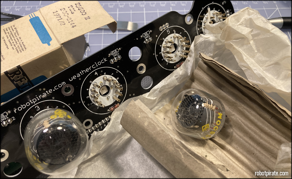
These haven't been seen or touched since 1971. 51 years old as of this writing, and they are beautiful! These tubes lack the red coating the normal z560m tubes have, and allow the NeoPixel backlight color to fully come through from the back.

All unwrapped and installed, and ready to see if they light up...

And they do! All functional, and working properly.
This site is part of the nonentity network. Not associated with LUCASFILM LTD.™ or any LFL Ltd.™ Film or Franchise.