
Here I will go through my assembly process for the Weatherclock
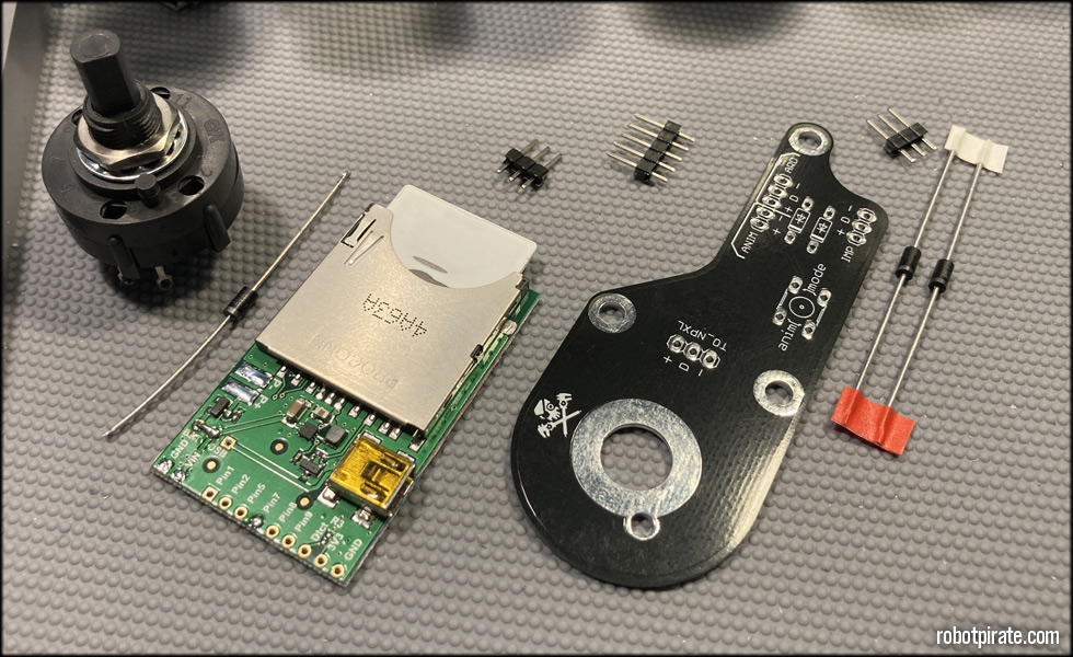
Here I am starting the assembly of the switch board and the modifications to the Electric Imp. From left:
3 position rotary switch to select backlight mode between Weather, Animation, and Off
IN4001 Diode to isolate t he power to the imp
Electric Imp WIFI board for connecting to the weather feed
Pin headers
Robotpirate Weatherclock Lefthand switch board, for passing NeoPixel power and data
2x IN4001 diodes to separate and isolate NeoPixel power between Imp and Arduino
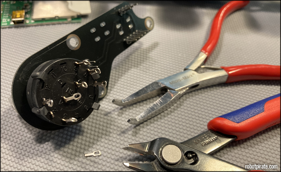
After installing the switch on the switchboard, and the pin headers, I bend the outer lead towards the middle of the clock, and cut the middle lead, as it won't be used.
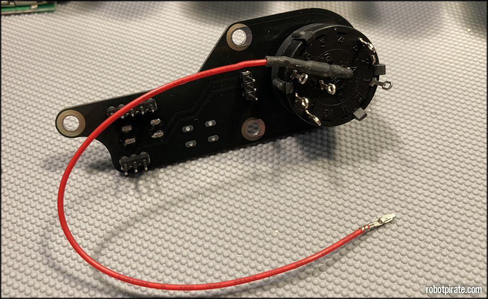
I have here a diode on the positive wire coming IN to the switch, but in later revisions I've moved this diode to the positive line going from the switch to the Electric Imp April board. This keeps the clock from resetting when switching to power on the Imp.
Version 1 of this board failed to include the ground connections to the groundplane, so I have to jumper those. Newer revisions of the board will have this fixed.
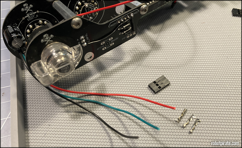
These leads are custom cut for the NeoPixel power and data from the switchboard to the display board. I'll custom crimp the ends and put a 3x connector housing on both ends.

These ends will be crimped and soldered, and inserted into the housing.
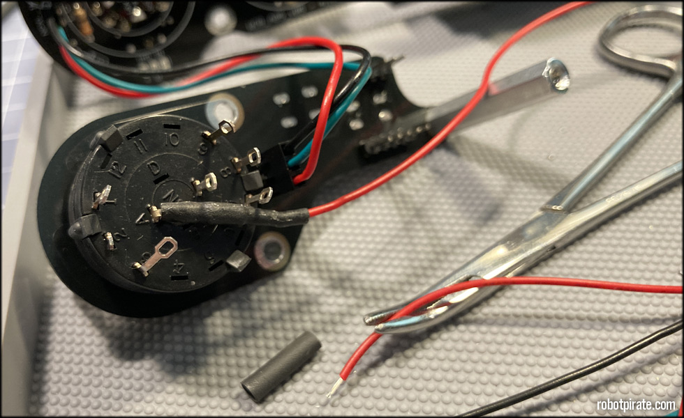
And then plugged in to the output header of the switchboard.
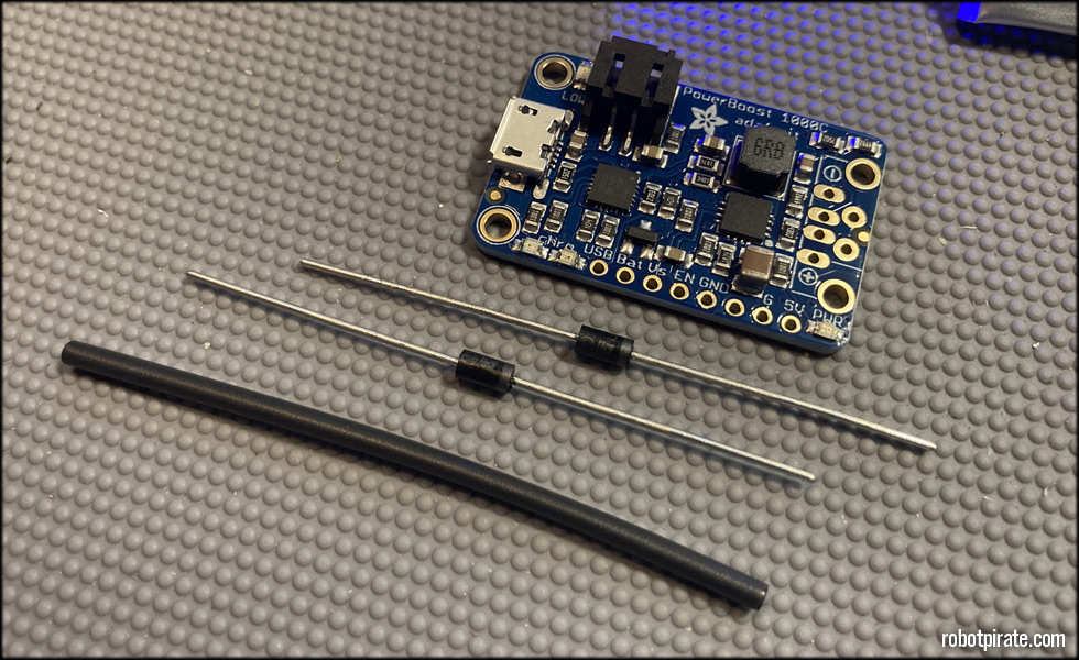
This is an Adafruit Powerboost 1000c. I will be using this to enable battery backup for time on the clock. I also need two IN4001 diodes and some small heat-shrink tubing.
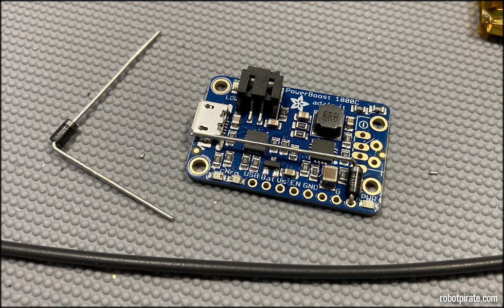
I bend one diode lead this way, and solder it in.
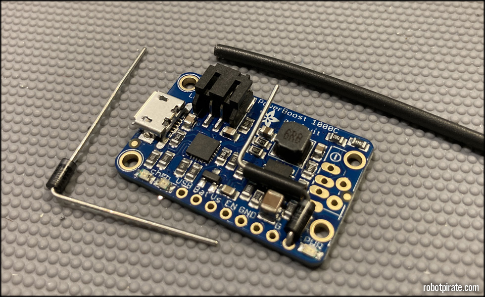
And bend further after the heat-shrink tubing is placed.
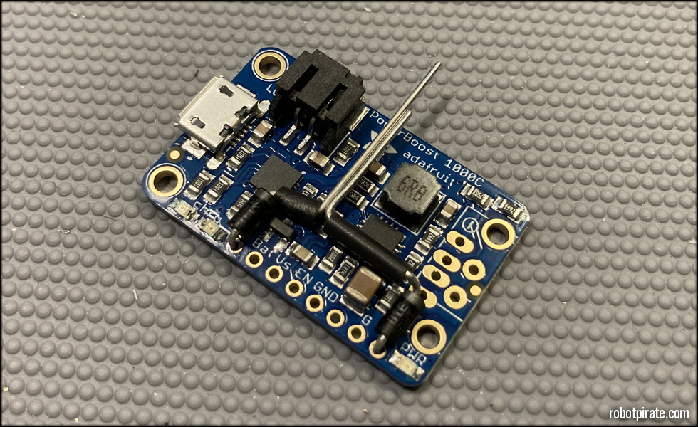
With both diodes installed, this is important because it allows the clock board to still sense the 60hz signal from the outlet when main power is supplied. When no main power is supplied, 5volts comes from the Powerboost and keeps the PIC processor going without supplying power to the add-ons such as the Electric Imp, Arduino, and main tubes power side.
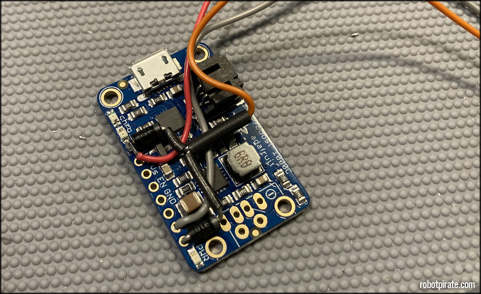
Red coming from the main clock board 5v supply, and orange going to where I've cut that 5v supply trace coming from C10 on the board.
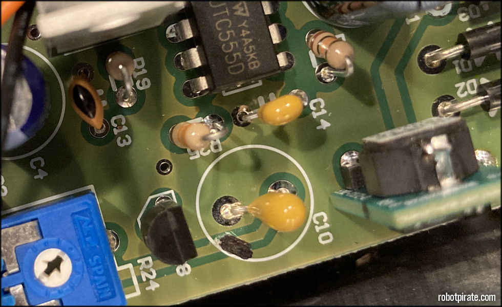
As the driver board comes, the output of the 5v module feeds directly to the PIC processor. If I want to introduce a battery backup solution that will keep the processor ticking, but not feed power to everything else that's on the 5v circuit, I cut the trace from C10 here, and insert my battery backup in between those to traces on the back of the board.
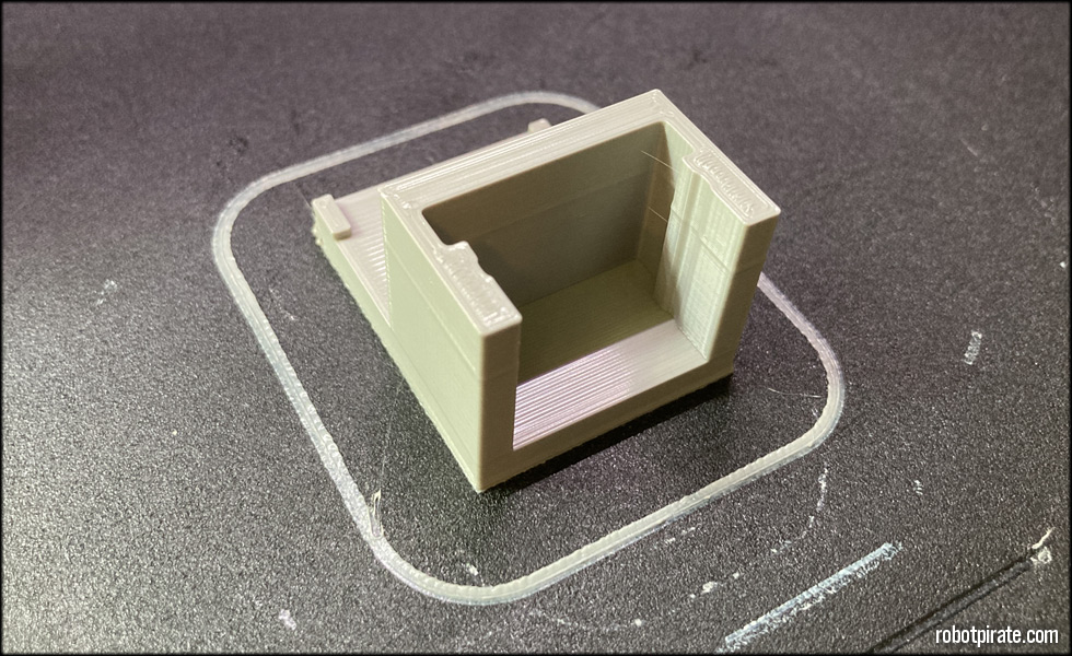
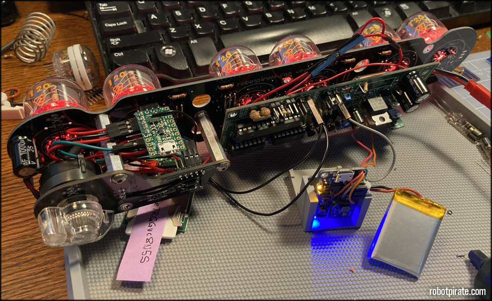
This is the 3D printed holder for the battery and the Powerboost. This keeps things safe inside the clock, as the battery backup solution was added later after the main clock internals were designed. It has a base which fits on the floor of the clock, and tabs on the back that fit under the driver board, keeping it secure.
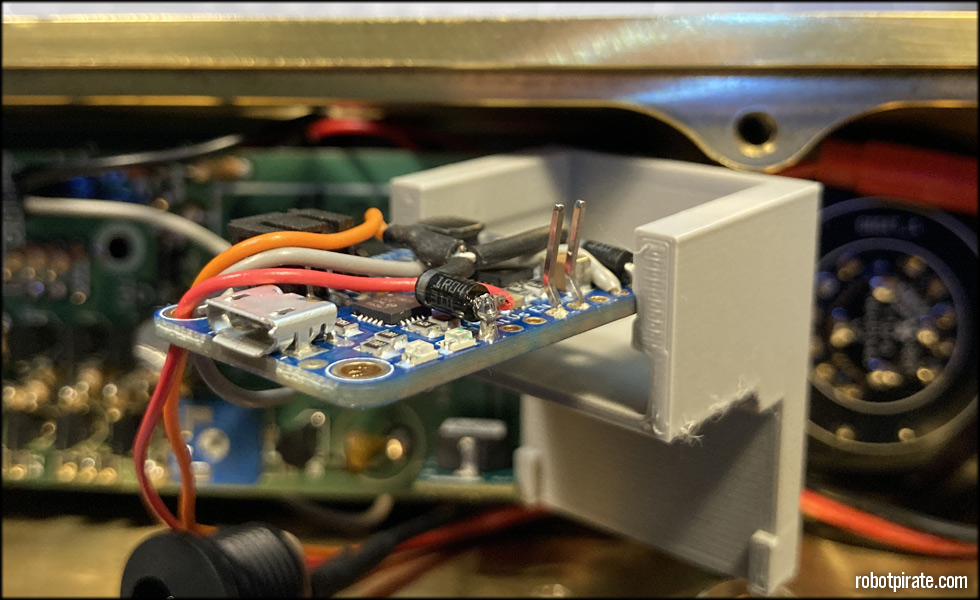
The grey wire coming from the ground tab of the Powerboost goes to one of the ground pin headers on the top of the driver board.
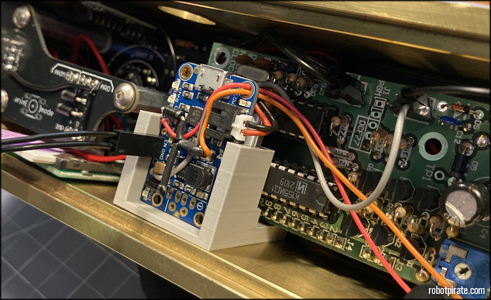
Once I tested this, I realized the Powerboost is ON by default. I need to be able to turn it OFF when the clock first boots up as having the power feed from the battery backup present on boot will interrupt the 60hz sensing the clock expects from the wall outlet. I need to be able to switch this board off at startup, so I added two pin headers for a remote switch. I will likely add this switch to one of the control switches on the back of the clock when done.
Here you can see where the battery backup housing fits into the back of the clock. This will have everything flush with the back plate of the clock.
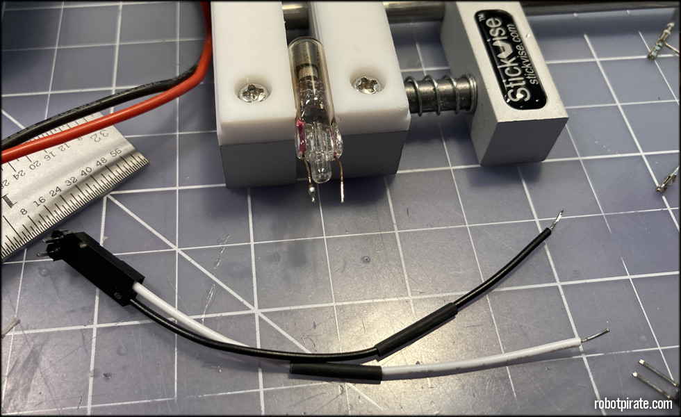
Next, I need to work up the INS-1 russian neon lamps. These will be inside the brass bezels in the front as colon separator lamps. I go through my box of new old stock INS-1 lamps till I find four that are matched in terms of brightness and quality, as these vary quite a bit. I then cut the long leads, and pre tin the leads of my wires. The anode is the side with a small dome of glass near the spot where the leads come out.
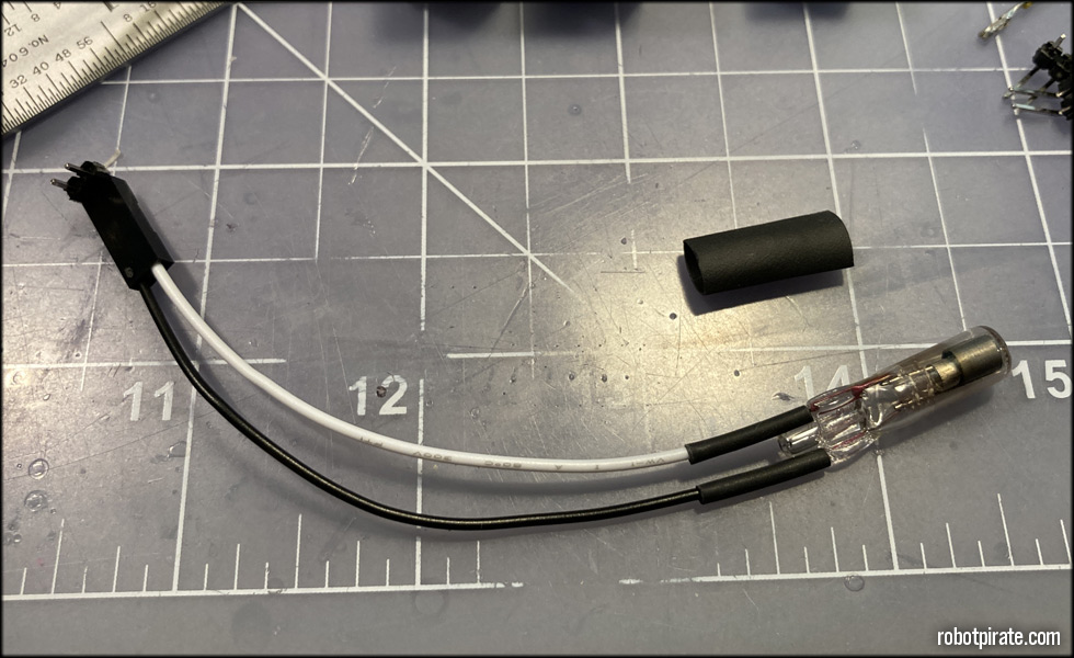
A bit of soldering and heat-shrink tubing, and this one is ready. A short length of larger diameter heat-shrink tubing is there to cushion the glass tube inside the brass bezel.
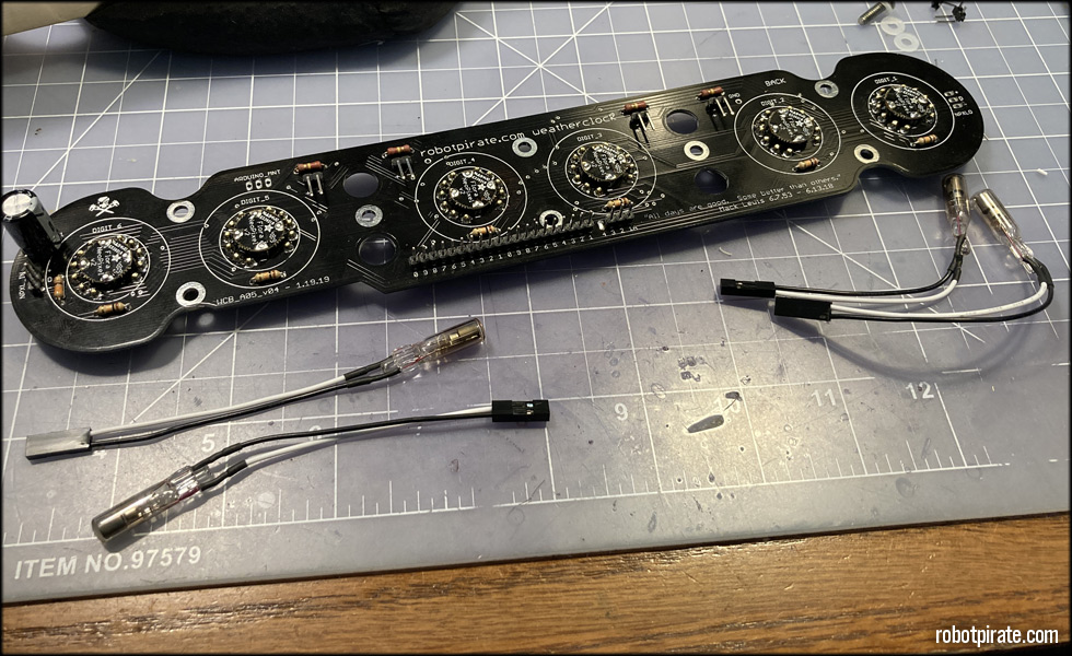
And here all four INS-1 lamps are ready. Two with slightly longer leads than the others, as one set will be closer to the headers than the other.
This site is part of the nonentity network. Not associated with LUCASFILM LTD.™ or any LFL Ltd.™ Film or Franchise.